![]()
Removal and Replacement Instructions for the VideoRay Pro 4
Dome Retaining Rings and Main Hull Rods
MHU-002-GY-KIT
![]()
|
|
Copyright
Pro 4 Maintenance Manual, Advanced 1.00.00 |
Copyright NoticeThis material is copyright protected. No material may be reproduced or transmitted in any form or by any means for any purpose without expressed written consent of VideoRay LLC. Copyright © 2015, VideoRay LLC - The Global Leader in Micro-ROV Technology |
|
|
Table of Contents
Pro 4 Maintenance Manual, Advanced 1.00.00 |
Table of Contents
|
|
|
About this Document
Pro 4 Maintenance Manual, Advanced 1.00.00 |
About this DocumentDocument ConventionsSeveral symbols are used throughout this documentation to add emphasis and to assist in relocating important information. The following table describes these symbols and their uses.
Beyond this DocumentThere is no substitute for experience and/or training, especially with respect to the real purpose for which you plan to use this equipment. We encourage you to explore options beyond the scope of these materials to expand your knowledge and skills necessary to support your applications. In addition to this documentation, VideoRay offers training and technical support and hosts a general user discussion forum and user image gallery. We also realize that collectively, users of our products spend considerably more time operating our systems than we do ourselves. Users also encounter more diverse operating environments across an extremely broad range of applications. We highly value this vast experience base, and invite and encourage you to share your experiences and suggestions with us. Please feel free to contact us by any of the methods listed below. Quality CommitmentVideoRay strives to design, manufacture, deliver and support the highest quality products and services, including this documentation. We have made every effort to ensure that this documentation is accurate and provides you with the most up-to-date information. If you find any errors in this documentation or have suggestions for improvements, each page contains a "Help us improve this document" feedback link in the left margin (you must be connected to the Internet to use this link).
DisclaimerThis document is deemed accurate at the time of its writing, however it is not a legal contract and the information contained herein should not be construed to represent any form of commitment. This document as well as the associated products and services are subject to change without notice. Online ManualThe full version of this manual is available online in the following formats:
|
|
|
How to Get Help
Pro 4 Maintenance Manual, Advanced 1.00.00 |
How to Get HelpHelp for your Pro 4 is available through several channels. All Hours Self-Service / Crowd-Source Tools
Global Support
Regional Support
Training
Operational Strategies and Tactics SupportIf you need help understanding how to apply your system to a specific project, contact VideoRay or you local VideoRay dealer. We can provide guidance or help you find a certified consultant. |
|
|
Removal Procedures
Pro 4 Maintenance Manual, Advanced 1.00.00 |
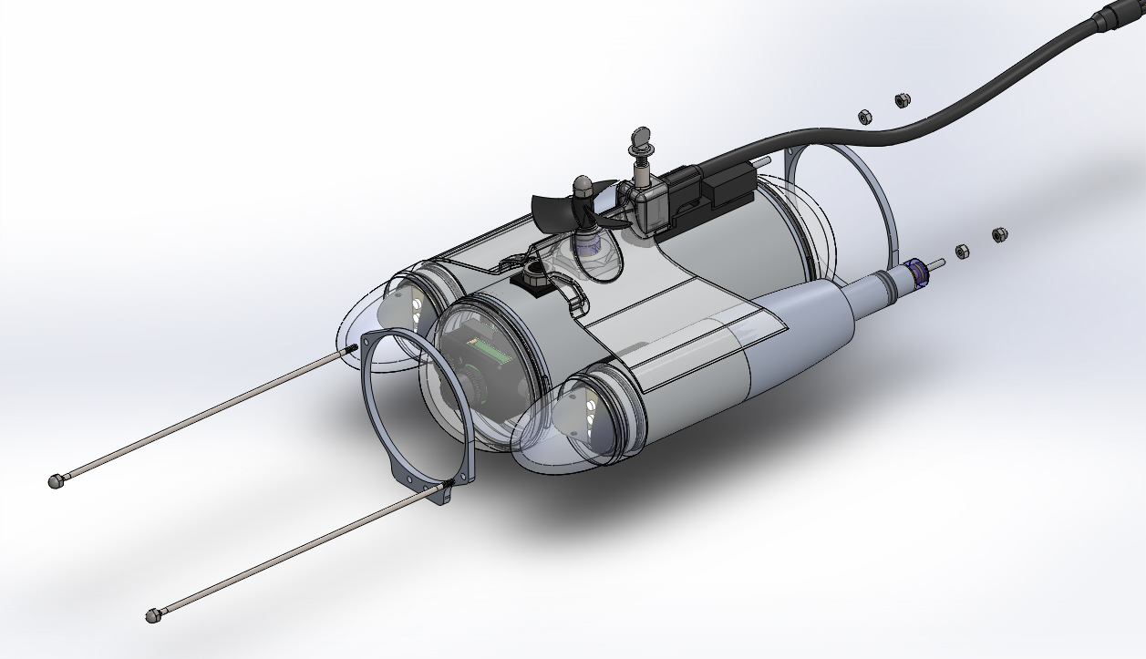
Dome Retaining Rings and Main Hull Rods Removal OverviewSkill level recommended: Intermediate Total time required: Approximately 20 Minutes Tools required:
The following components must be removed:
See the corresponding sections of this manual for instructions for parts other than the Dome Retaining Rings and Main Hull Rods. |
|
|
5 - Dome Retaining Rings
Pro 4 Maintenance Manual, Advanced 1.00.00 |
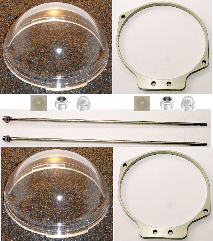
Dome Retaining Rings and Main Hull Rods Removal ProceduresTime required for this step: Approximately 5 Minutes Tools required for this step: Parts involved in this step: MHU-002-GY-KIT Dome Retaining Rings and Main Hull Rods
Steps
Tip
It is usually best to leave the main hull rods in the front dome retaining ring unless you are replacing the retaining ring or rods. |
|
|
Replacement Procedures
Pro 4 Maintenance Manual, Advanced 1.00.00 |
Dome Retaining Rings and Main Hull Rods Replacement OverviewSkill level recommended: Intermediate Total time required: Approximately 20 Minutes Tools required:
The following components must be replaced:
See the corresponding sections of this manual for instructions for parts other than the Dome Retaining Rings and Main Hull Rods. |
|
|
1 - Dome Retaining Rings
Pro 4 Maintenance Manual, Advanced 1.00.00 |
Dome Retaining Rings and Main Hull Rods Replacement ProceduresTime required for this step: Approximately 5 Minutes Tools required for this step:
Parts involved in this step: MHU-002-GY-KIT Dome Retaining Rings and Main Hull Rods
Steps
TipThe front and rear dome rings are identical and can be interchanged. |