Note: The following step-by-step instructions apply to one side. Repeat these steps on both sides if you are replacing both Horizontal Thrust Tubes.
Apply Tef-Gel to the main hull in the areas where the horizontal thruster tube spacers will contact the hull. Do NOT get Tef-Gel too close to the screw holes.
Place the two #8 SS washers on the two 8-32 X 3/4 inch socket cap screws and insert the socket screws with washers through the flat side of the "inside" horizontal thruster tube spacer.
From inside the main hull, install the two socket screws and spacer. The curved side of the spacers should be towards the hull.
Apply blue Loctite to the screw threads
Lubricate and install the #122 O-rings on both sides of the "between hulls" thruster tube spacers.
Orient the "between hulls" horizontal thruster tube spacers so that the notch is facing toward the front of the ROV and away from the main hull. The "between hulls" thruster tube spacer has two concave diameters to match the main hull and the thruster tube diameters. If installed incorrectly, the spacer will leak. When oriented with the notch away from the main hull, the "between hulls" thruster tube spacer's concave surfaces will match the corresponding component diameter.
Place the "between hulls" horizontal thruster tube spacer in position over the two socket screws.
Orient the horizontal thruster tube along side of the main hull with the holes for the wire harness aligned and the external threads for the light dome towards the front of the ROV.
Make sure the #122 O-rings are in position and will not be pinched.
Thread the socket screws into the horizontal thruster tube and tighten them evenly to 35 inch-pounds (3.95 Nm).
If the video above doesn't play in your browser, click this play icon to try an alternate method: ,
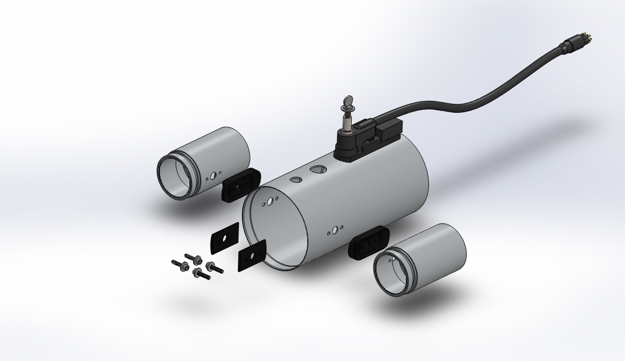
or click this manual reference icon to view an exploded view