If not installed, install the ribbon cable in the ROV power board and secure the ribbon cable connector clamp.
Orient the ROV CPU board above the ROV power board so that the navigation module socket is over the large capacitors and the ribbon cable connectors on the board are both oriented up and on the same side.
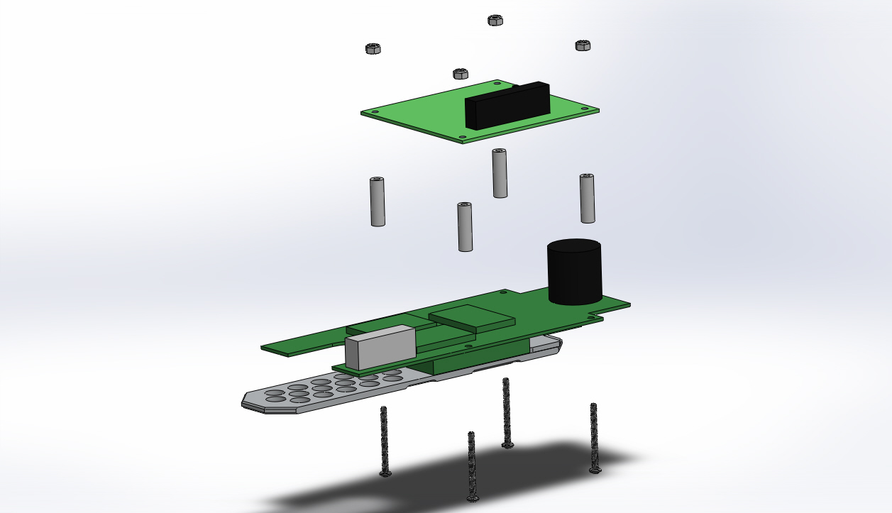
Align both boards so that the four mounting holes line up.
Replace the four 4-40 X 1-1/4 inch Phillips head screws through the ROV power board from the bottom and then through the #4 X 7/8 inch spacers and then through the CPU board.
Replace the four 4-40 Nylock nuts on the screws on the top side of the ROV CPU Board and tighten the nuts.
Replace the ribbon cable in the ROV CPU board and secure the ribbon cable connector clamp.
If the video above doesn't play in your browser, click this play icon to try an alternate method: ,
or click this manual reference icon to view an exploded view