Apply Tef-Gel to the outside of the main hull in the area where the termination block plate will contact the hull. Do NOT get Tef-Gel too close to the holes.
Lubricate and install the #014 O-ring over the accessory port connector stud.
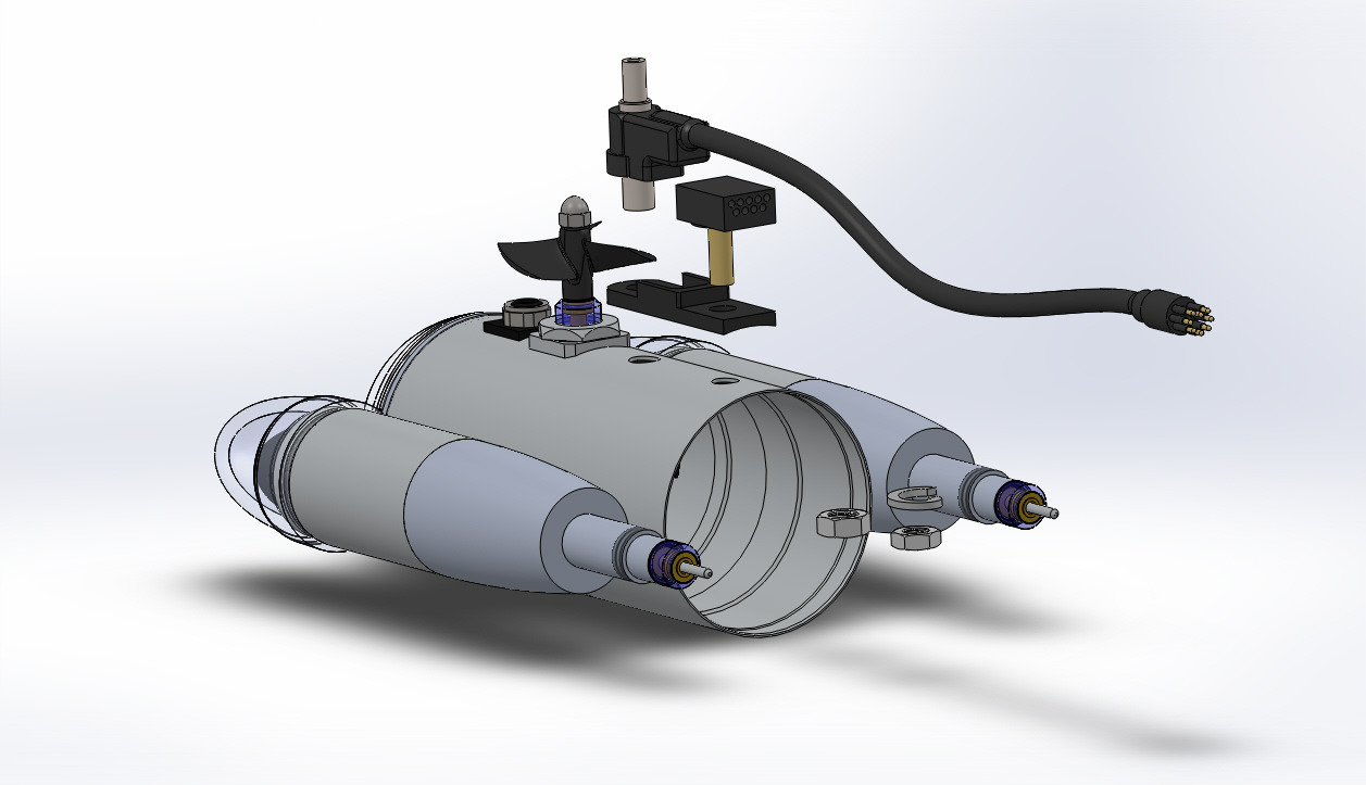
Place the accessory port connector through rear hole of the termination block plate, with the connector facing toward the rear. The rear hole is closer to the straight edge. The wires should come through the termination block plate on the side with the curved face.
Lubricate and install the #017 O-ring over the termination block stud.
Place the termination block through the front hole of the termination block plate, with the ROV whip over the accessory port connector. The front hole is closer to the curved edge. The wires should come through the termination block plate on the side with the curved face.
Lubricate and install an #114 O-ring over the accessory port connector stud.
Lubricate and install an #114 O-ring over the termination block stud.
Feed the wires from both connectors through the top holes in the main hull.
Pass the wires from the termination block through a termination block spacer and place the spacer over the termination block stud the curved surface of the spacer towards the hull.
Apply blue Loctite to the threads of the termination block stud.
Pass the wires from the termination block through the termination block 1/2-13, 3/4 inch nut and place the nut over the termination block stud, but do not tighten it all of the way.
Pass the wires from the accessory port connector through a termination block spacer and place the spacer over the accessory port connector stud the curved surface of the spacer towards the hull.
Apply blue Loctite to the threads of the accessory port connector stud.
Pass the wires from the accessory port connector through the accessory port connector washer and place the washer over the accessory port connector stud.
Pass the wires from the accessory port connector through the accessory port 7/16-20, 11/16 inch nut and place the nut over the accessory port connector stud, but do not tighten it all of the way.
Tighten each nut equally a small amount at a time to 60 inch-pounds (6.8 Nm).
Replace the wires into the appropriate slots in the connectors using the tables below.
Connector 10 x 2
Wire
1
Termination Block (8 wires) Pin 1 (Video -)
2
Termination Block (8 wires) Pin 2 (Video +
3
No Connection
4
Termination Block (8 wires) Pin 4 (AUX)
5
No Connection
6
Termination Block (8 wires) Pin 6 (AUX)
7
Termination Block (8 wires) Pin 8 (RS-485 -)
8
Termination Block (8 wires) Pin 7 (RS-485 +)
9
Ground Wire
10
No Connection
11
Accessory Port Connector (9 wires) Socket 1 (Video -)
12
Accessory Port Connector (9 wires) Socket 2 (Video +)
13
No Connection
14
Accessory Port Connector (9 wires) Socket 4 (AUX)
15
No Connection
16
Accessory Port Connector (9 wires) Socket 6 (AUX)
17
Accessory Port Connector (9 wires) Socket 7 (RS-485 +)
18
Accessory Port Connector (9 wires) Socket 8 (RS-495 -)
19
No Connection
20
No Connection
Connector 8 x 2 (ROV Wire Harness)
Wire
1
Right (Starboard) Thruster Yellow
2
Right (Starboard) Thruster Green
3
Vertical Thruster Blue
4
Left (Port) Thruster Blue
5
Left (Port)thruster Green
6
Lights Red
7
Accessory Port Connector (9 wires) Socket 9 (12 V DC)
8
Termination Block (8 wires) Pin 3 (73 V DC)
9
Accessory Port Connector (9 wires) Socket 3 (24 V DC)
10
Right (Starboard) Thruster Blue
11
Vertical Thruster Yellow
12
Vertical Thuster Green
13
Left (Port) Thruster Yellow
14
Lights Black
15
Accessory Port Connector (9 wires) Socket 5 (Ground)
16
Termination Block (8 wires) Pin 5 (Ground)
If the video above doesn't play in your browser, click this play icon to try an alternate method: ,
or click this manual reference icon to view an exploded view
Product Update
Some ROVs may have a green/yellow ground wire connected to the termination block. This has been removed in newer models that have the latest pressure sensor. If the ROV has a white housing pressure sensor, the ground wire should not be used. If the ROV has a black housing pressure sensor, the ground wire must be used.