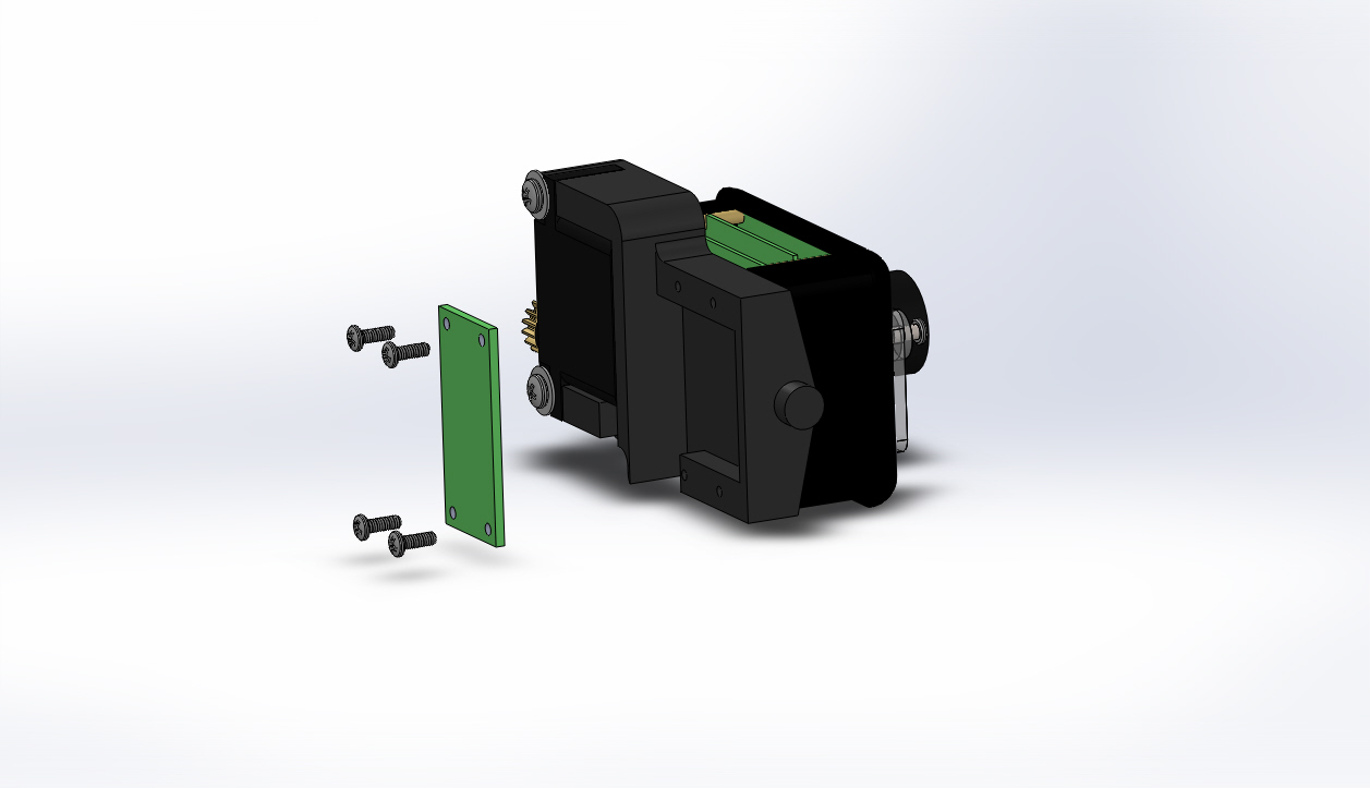
Unscrew the four 2-56 X 1/4 inch Phillips head screws that hold the camera interface board to the camera mount base.
Follow one of the options below:
If you are removing the camera interface board, unsolder the wires from the camera connector and camera tilt and camera focus servo motors.
If you are removing the camera focus servo motor, unsolder the wires from the focus servo to the interface board.
If you are removing the camera tilt servo motor, unsolder the wires from the tilt servo to the interface board.
If you are removing the camera, camera mount cover or camera mount base, you do not need to unsolder the wires from the camera interface board. The camera has a connector at the camera and will only need to be unsoldered if you are replacing the camera interface board.
If the video above doesn't play in your browser, click this play icon to try an alternate method: ,
or click this manual reference icon to view an exploded view