Connect the camera ribbon cable to the camera interface board.
Connect the ROV to the control panel, and turn on the control panel briefly and then turn it off. This will center the camera tilt servo motor.
Disconnect the camera ribbon cable from the camera interface board.
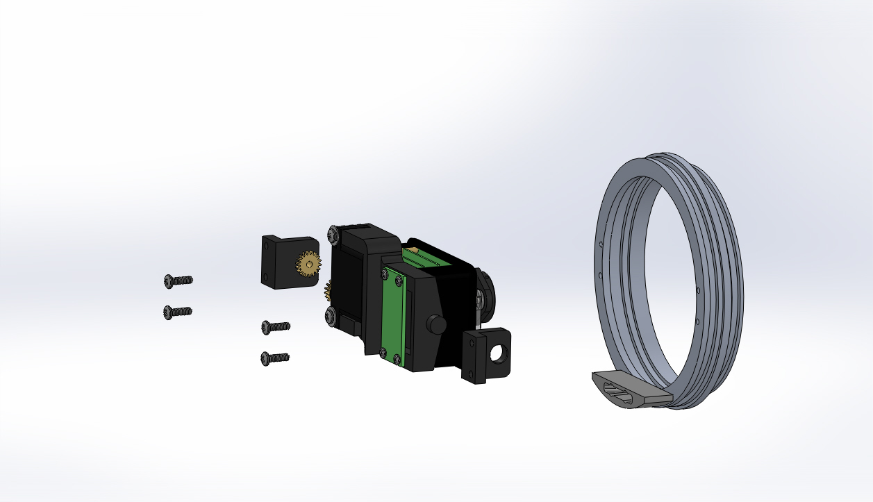
Orient the port camera bracket (the one with the gear) on the port side of the camera assembly (the side with the tilt servo motor). The tab with the two holes should be pointed away from the camera assembly and on the rear side of the camera assembly. The tab with the two holes should also be parallel to the plane of the hull ring.
Place the port camera bracket with the tilt gear over the shaft on the port side of the camera mount.
If the tab with the two holes is not parallel to the plane of the hull ring after engaging the gears, remove the bracket, remove the gear from the tilt servo motor shaft and rotate the gear one tooth on the tilt servo motor shaft and try again. Replace the bracket and check the alignment. Repeat this process until the tab with the two holes is parallel to the plane of the hull ring.
Orient the starboard camera bracket on the starboard side of the camera assembly with the tab with the two holes pointed away from the camera assembly and on the rear side of the camera assembly. The tab with the two holes should be parallel to the plane of the hull ring.
Place the starboard camera bracket over the boss on the starboard side of the camera mount.
Orient the front hull ring with the receiver bracket on the bottom.
Replace the camera assembly and brackets into the front hull ring from the side with the receiver bracket.
Replace the four 4-40 X 3/8 inch Phillips head screws in the camera brackets and tighten the screws.
If the video above doesn't play in your browser, click this play icon to try an alternate method: ,
or click this manual reference icon to view an exploded view
Tips
If the gears are difficult to engage, you can loosen the two screws that hold the camera tilt servo motor to the camera mount base. This should allow enough clearance for the gears to engage easily. Make sure to tighten the screws after the gears are engaged. Also make sure the washers are positioned over the tilt servo motor to keep it from coming loose.
Before proceeding to the next step, connect the ROV to the control panel and test the camera tilt function to make sure the camera tilts smoothly through the entire tilt range.