If necessary, solder the wires from the camera connector cable to the camera interface board.
If necessary, solder the wires from the camera tilt servo motor to the camera interface board.
If necessary, solder the wires from the camera focus servo motor to the camera interface board.
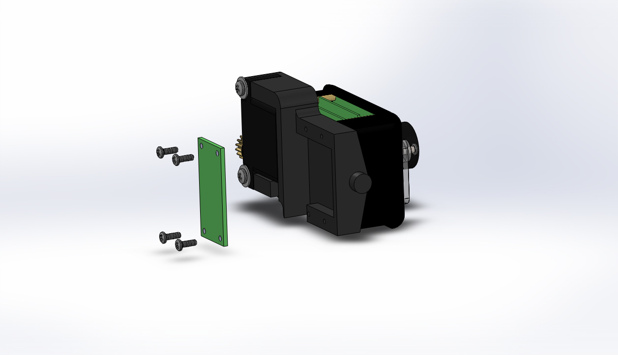
Replace the four 2-56 X 1/4 inch Phillips head screws that hold the camera interface board to the camera mount and tighten the screws.
Align the camera connector cable's pins with those of the camera connector on the rear of the camera and connect the camera connector cable to the camera.
If the video above doesn't play in your browser, click this play icon to try an alternate method: ,
or click this manual reference icon to view an exploded view