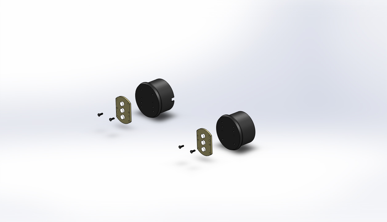
LED Light Printed Circuit Board Replacement Procedures

Time required for this step: Approximately 5 Minutes (10 Minutes for both sides)

Tools required for this step:

Parts involved in this step:

VR-PRO4-05-0002 LED Light Printed Circuit Board

QuantityPart NumberPart Description
1VR-PRO4-05-0002Circuit Board ROV LED Lights (Pro 4 front)
291249A050Screw #2-56 x 1/4" Pan Head Phillips SS Black
1WM1845-NDConnector 2 x 1 Molex Micro-Fit Female
2538-43030-0010Crimp Pin 26-30 AWG Molex Micro-Fit Female

Steps

Note: The following step-by-step instructions apply to one side. Repeat these steps on both sides if you are replacing both LED Light Boards.

  1. Orient the LED light board (with the LEDs facing out) on the front face of the LED light mount and align the eight holes. If all of the holes are not aligned, rotate the LED light board 180 degrees.

  2. Insert the 2-56 X 1/4 inch Phillips head LED light board screws through the center holes in the front of the LED light module into the LED light mount and tighten the screws.

  3. Insert the red wire from the wire connector through the "+" side from the rear of the LED light mount and solder it to the "+" solder pad. Make sure the solder or wire does not touch the screw.

  4. Insert the black wire from the wire connector through the "-" side from the rear of the LED light mount and solder it to the "-" solder pad. Make sure the solder or wire does not touch the screw.

If the video above doesn't play in your browser, click this play icon to try an alternate method: , or click this manual reference icon to view an exploded view

Tip

VideoRay recommends that you test the LED light board for a short between the wires and the LED board base and test the light board in a known working ROV before replacing the remaining LED light module parts.


VideoRay Documentation Only

[ Help us improve this document ]

Pro 4 Maintenance Manual, Version: Advanced 1.00.00
Copyright © 2015, VideoRay LLC - The Global Leader in Micro-ROV Technology