ROV CPU Printed Circuit Board Removal Procedures

Time required for this step: Approximately 5 Minutes

Tools required for this step:

Parts involved in this step:

PRO4-SUB-CPU19 ROV CPU Printed Circuit Board

QuantityPart NumberPart Description
1PRO4-SUB-CPU19Circuit Board ROV CPU (Pro 4)
1HF30U-03-NDCable 3" Ribbon 30 Conductor
491772A116Screw #4-40 x 1-1/4" Pan Head Phillips SS
491831A005Nut #4-40 x 1/4" Nylock
4881K-NDSpacer #4 x 7/8" Nylon

Steps

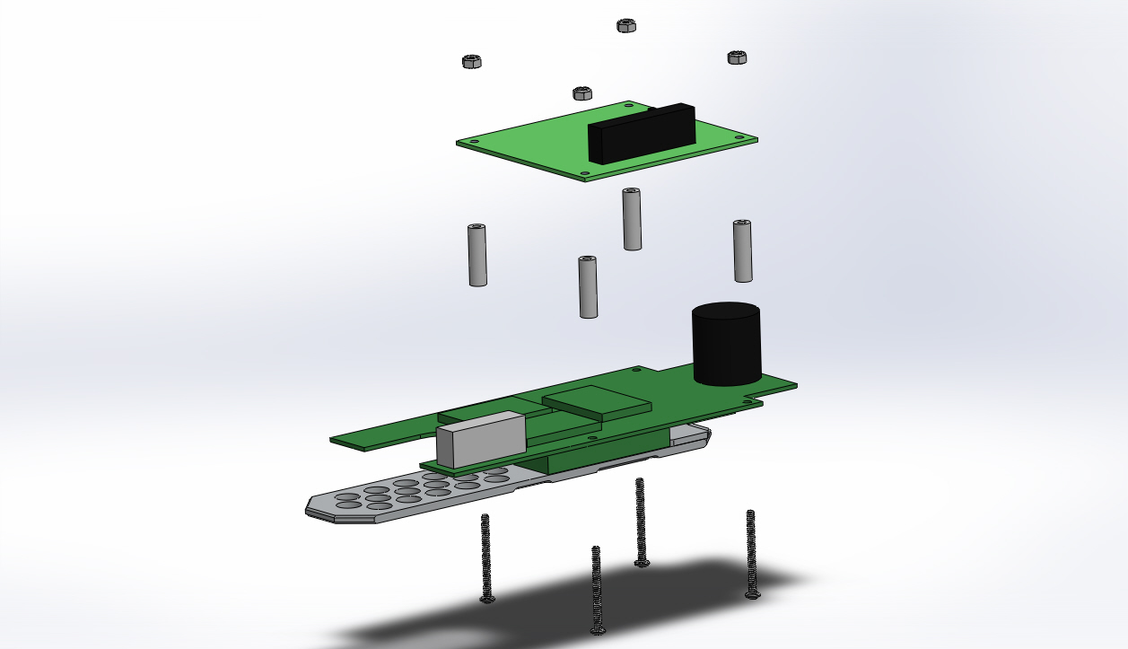
  1. Loosen the ribbon cable connector clamp on the ROV CPU board, and disconnect the ribbon cable from the ROV CPU board.

  2. Remove the four 4-40 Nylock nuts that hold the ROV CPU board to the ROV power control board.

  3. Separate the ROV CPU board from the ROV power control board.

  4. Remove the four #4 X 7/8 inch spacers and 4-40 X 1-1/4 inch Phillips head screws from the ROV power control board.

If the video above doesn't play in your browser, click this play icon to try an alternate method: , or click this manual reference icon to view an exploded view


VideoRay Documentation Only

[ Help us improve this document ]

Pro 4 Maintenance Manual, Version: Advanced 1.00.00
Copyright © 2015, VideoRay LLC - The Global Leader in Micro-ROV Technology