Using a dental pick or similar instrument, remove the termination block and accessory port wires from the ROV CPU board connector.
Unlatch the ROV power control board connector latches and remove the termination block and accessory port wires from the ROV power control board connector.
From inside the main hull, remove the 7/16-20, 11/16 inch nut and washer from the accessory port connector.
From inside the main hull, remove the 1/2-13 and 3/4 inch nut from the termination block.
Lift the termination block, accessory port connector and termination block plate from the top of the ROV.
Separate the termination block and accessory port connector from the termination block plate.
If the video above doesn't play in your browser, click this play icon to try an alternate method: ,
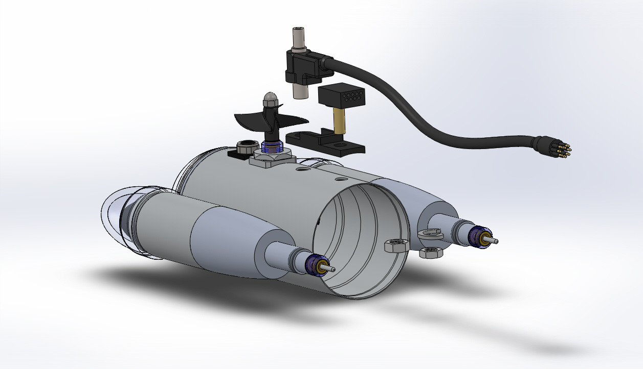
or click this manual reference icon to view an exploded view
Tip
Be careful when removing the wires from the connectors. If you break the crimps, you will need to replace them before you can replace the termination block.